
Released on September 28, 2025
Godot 4 Anime Shader: The Definitive Cel Shading & Outline Guide
TAchieve the perfect professional anime look. This step-by-step masterclass covers custom cel shading and high-quality outlines in Godot 4 using the Visual Shader editor.
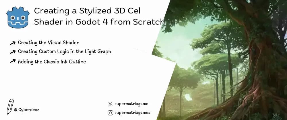
Table of Contents#
- Introduction: The Art of Non-Photorealistic Rendering
- Step 1: Preparing Your 3D Test Scene
- Step 2: Creating Your First Visual Shader
- Step 3: Calculating Light for Hard Shadows
- Step 4: The Magic of the
step()Function - Step 5: Adding the Classic Ink Outline
- Conclusion: A New Stylistic Tool in Your Arsenal
Introduction: The Art of Non-Photorealistic Rendering #
Photorealism is impressive, but some of the most visually stunning games embrace a stylized, artistic look. Cel shading (also known as toon shading) is a non-photorealistic rendering technique that makes 3D models look like they were hand-drawn in a 2D cartoon or anime. It's characterized by flat lighting, hard-edged shadows, and crisp outlines.
In this guide, we'll build a simple but effective 3D cel shader from scratch using the node-based Visual Shader editor, using the correct shader graphs for each operation.
Step 1: Preparing Your 3D Test Scene #
First, we need a simple scene to test our shader.
- Create a new 3D Scene.
- Add a MeshInstance3D node (e.g., with a
SphereMesh). - Add a DirectionalLight3D to cast light.
- Add a WorldEnvironment node for basic lighting.
- Add and position a Camera3D.
Step 2: Creating the Visual Shader #
Now, let's create the shader resource.
- Select the MeshInstance3D node.
- In the Inspector, go to
Geometry > Material Overrideand selectNew ShaderMaterial. - Click the new material, and for its
Shaderproperty, selectNew VisualShader. - Click the VisualShader resource to open the editor.
In the Fragment Graph, which is shown by default, we will only set the base color.
- Right-click and add a
VectorConstant. This will be your object's color (e.g., a nice orange). - Connect its output to the
Albedoinput on the Output node.
Step 3: Creating Custom Logic in the Light Graph #
To create the hard-edged shadow, we need to tell the renderer how to calculate light hitting our object. This logic belongs in the Light graph.
- At the top of the Visual Shader Editor, click the Light button to switch to the Light graph.
- In this graph, add an
Inputnode forNormaland another forLightVector. - Add a
DotProductnode and connectNormalandLightVectorto its inputs.
Step 4: The Magic of the step() Function #
Now we'll turn the smooth light gradient from the dot product into a sharp line.
- Add a
Stepnode and connect theDotProductoutput to itssampleinput. - Add a
ScalarConstant(e.g., value0.5) and connect it to theedgeinput of theStepnode. - Add a
Mixnode. Connect theStepoutput to itsweightinput. - For the first
Mixinput, use a blackVectorConstantfor the shadow. - For the second
Mixinput, add anInputnode forLightto get the light's actual color. - Connect the final
Mixoutput to theDiffuseinput on the main Output node.
Step 5: Adding the Classic Ink Outline #
The final touch is the outline, which uses the inverted hull method. This requires manipulating the model's vertices, so it is done in the Vertex graph.
- Select your main ShaderMaterial in the Inspector. Find the
Next Passproperty and assign aNew ShaderMaterialto it. - Create a
New VisualShaderfor this "Next Pass" material. - Open this new outline shader and click the Vertex button at the top to switch to its Vertex graph.
- In the shader's settings (click an empty space in the graph), go to Render Mode and set
culltofront. This makes the "inside" of the enlarged mesh visible, which creates the outline.
Now, let's build the vertex offset logic with explicit steps:
- Get Vertex Normal: Add an
Inputnode. By default, its type isNormal, which is what we need. This tells us the direction to push the vertex. - Define Outline Thickness: Add a
ScalarConstant(e.g.,0.02). - Calculate Offset: Add a
VectorOperators > Multiplynode. Connect theNormalinput and theScalarConstantto it. The result is our offset vector. - Get Original Vertex Position: Add another
Inputnode. With this node selected, go to the Inspector panel. Click the dropdown for theInputproperty and change it fromNormaltoVertex. This is the crucial step. You now have access to the model's original vertex positions. - Combine and Output: Add a
VectorOperators > Addnode. Connect the output of yourVertexinput node and your offset (from theMultiplynode) into it. - Connect the final result from the
Addnode to theVertexinput on the main Output node.
Finally, click the Fragment button for this outline shader. Since the outline should just be a solid color, add a black VectorConstant and connect it to the Albedo output.
Conclusion: A New Stylistic Tool in Your Arsenal #
By correctly placing logic in the Light graph for custom lighting and the Vertex graph for model manipulation, you have now created a complete, stylized cel shader. Understanding which graph to use—and how to access the correct inputs like Vertex—is key to unlocking the power of Godot's shader system.
Continue Reading
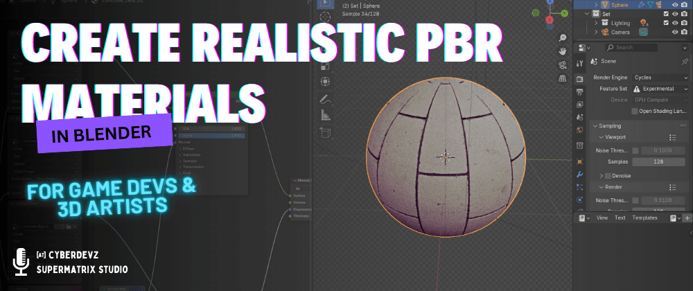
Godot 4 PBR Checklist: Get Perfect Blender Materials Every Time
Stop guessing why your materials look different in Godot. This guide covers the exact baking settings and glTF export parameters needed to maintain PBR accuracy from Blender to Godot 4.
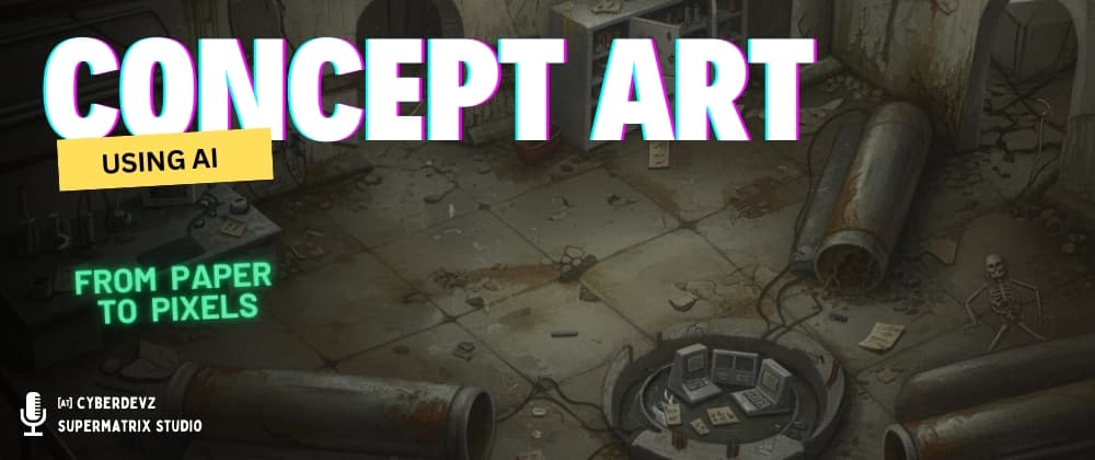
How did I Create Concept Arts using AI
Discover how to create stunning concept art with AI using our step-by-step guide. Learn the complete workflow, using the right tools and methods